LED
Description
LEDs are most common as simple visual output. LED stands for light-emitting diode (https://en.wikipedia.org/wiki/Light-emitting_diode).
LEDs have 2 connectors: anode (+, long leg) and cathode (-, short leg)
The direction in which the LED is put into the circuit is important. For the forward direction and this is what we want, as this is when the LED is lighting up, the cathode (-, short leg) has to go towards 0V/GND and the anode (+, long leg) towards 3.3V/+/VSS.
A LED typically requires a resistor that is in series with the LED to restrict the current that is flowing through the LED.
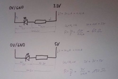
For sketching we can just use the following values (see #Background for more details):
- 100 Ohm for a controller with 3.3V (our ESP32/ESP8266)
- 150 Ohm, 200 Ohm or 330 Ohm for a controller with 5V
How to connect it electrically
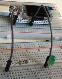
This is how to connect an LED to a power supply. It does not matter where the resistor goes. But if the direction of the LED is wrong, it will not light up.
LED will be on if Pin26 is 3.3V (or ON or High)
LED will be on if Pin26 is 0V (or OFF or Low)
How to control it in MicroPython
from machine import Pin
# assume our LED is connected to Pin 26, we use it as output
myLED = Pin(26, Pin.OUT)
# this switches the LED on
myLED.on()
# this switches the LED off
myLED.off()
A small Program in MicroPython
from machine import Pin
from time import sleep

# assume our LED is connected to Pin 26, we use it as output
myLED = Pin(26, Pin.OUT)

while True:
      # this switches the LED on for 1 second
      myLED.on()
      sleep(1)
      # this switches the LED off for 500 ms
      myLED.off()
      sleep(0.5)
The setup to try the program:
Related Tutorial Videos
Background
For an LED we are interested in the following parameters:
- the forward voltage (typically about 2V)
- the forward current (typically about 20mA = 0,02A)
We use the equations R=U/I and U=U1+U2 to calculate the resistor required.


