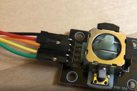
Analog Joystick
Jump to navigation
Jump to search
Description
The analog joystick includes 2 Potentiometer and one digital switch.
It has 5 connectors:
- GND - connected to GND
- 5V - which is in our cases connected to 3.3V
- VRx - the voltage representing the position in X
- VRy - the voltage representing the position in Y
- SW - 0 if pressed
How to connect it electrically
How to control it in MicroPython
Reading all values and printing them to the console
#Example usage for ESP32
from machine import Pin, ADC
from time import sleep
# analog inputs for X and Y
analogPinX = ADC(Pin(34))
analogPinY = ADC(Pin(35))
#switching the analog input to 12Bit (0...4095)
analogPinX.atten(ADC.ATTN_11DB)
analogPinY.atten(ADC.ATTN_11DB)
# digital input on pin 26
sw = Pin(26, Pin.IN, Pin.PULL_UP) # enable internal pull-up resistor

while True:
  analogValX = analogPinX.read()
  analogValY = analogPinY.read()
  switch = sw.value()

  print("x:%s   y:%s   sw:%s" % (analogValX, analogValY, switch))

  sleep(1)
Related Tutorial Videos
Background
This is conceptually what is inside the joystick.


