Difference between revisions of "SG90 Servo"
| Line 78: | Line 78: | ||
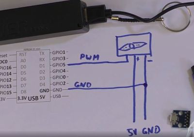
[[File:PowerUSB.JPG|400px]] | [[File:PowerUSB.JPG|400px]] | ||
| − | [[File:PowerUSB-module.JPG| | + | [[File:PowerUSB-module.JPG|100]] |
[[File:PowerUSB-setup.JPG|400px]] | [[File:PowerUSB-setup.JPG|400px]] | ||
Revision as of 11:38, 29 December 2020
Contents
IMPORTANT
In many computers the current is not enough to drive the servo!!!
If it does not work, keeps disconnecting, or rebooting the ESP the power is not sufficent and you need a capacitor ot an extra power supply.
See the video for details how to do this.
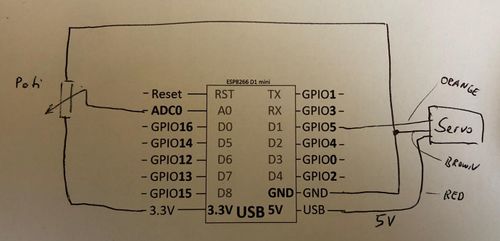
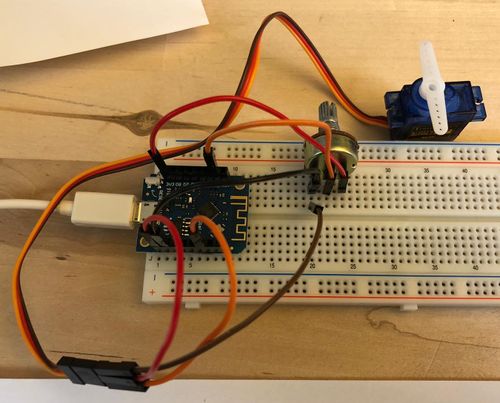
Schematic - Connecting the SG90
Code Examples ESP8266
Basic control
Assuming the servo is connected to Pin 5.
 1 from machine import Pin,PWM
 2 from time import sleep
 3
 4 servoPin = Pin(5, Pin.OUT)
 5 pwm =  PWM(servoPin, freq=50)
 6 pwm.deinit() # workaround to reset PWM
 7 pwm = PWM(servoPin, freq=50)
 8
 9 val = 50
10
11 while True:
12   pwm.duty(val)
13   val = val + 1
14   if val>100:
15     val = 50
16   print(val)
17   sleep(0.05)
Controlling the servo with a Poti
A0 is the analog input with 10 bit resolution. It reads the analog value every second and print it to the console and sets the servo based on the analog input.
 1 from machine import Pin, ADC, PWM
 2 from time import sleep
 3
 4 analogPin = ADC(0)
 5 servoPin = Pin(5, Pin.OUT)
 6 pwm =  PWM(servoPin, freq=50)
 7 pwm.deinit()
 8 pwm = PWM(servoPin, freq=50)
 9
10 while True:
11   analogVal = analogPin.read()
12   pwm.duty(int(analogVal/10))
13   print(analogVal)
14   sleep(1)
Related Tutorial Videos
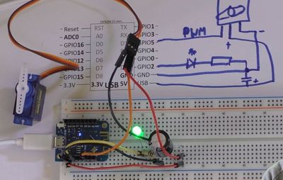
PWM Output: connecting a servo and and LED
Power Issues
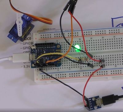
When connecting the servo to the ESP32 or ESP8266 it may not work at all, may restart at random times, or may move to a wrong angle. This is typically a power issue. The ESP-board is and the USB-output of the computer does not provide enough power. There are two fixes: adding a big capacitor (e.g. 2000 uF) or adding an external power source. The external power source is the better solution.
Have a look at the video for details.
