Circuitpython: Difference between revisions
m Reverted edits by Skwhadmin (talk) to last revision by 79.215.30.235 Tag: Rollback |
|||
| (33 intermediate revisions by 2 users not shown) | |||
| Line 5: | Line 5: | ||
Go to [https://circuitpython.org/downloads circuitpython.org/downloads] and download the version for your board. | Go to [https://circuitpython.org/downloads circuitpython.org/downloads] and download the version for your board. | ||
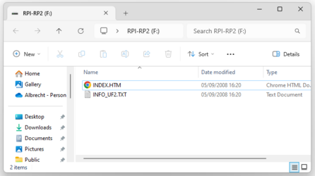
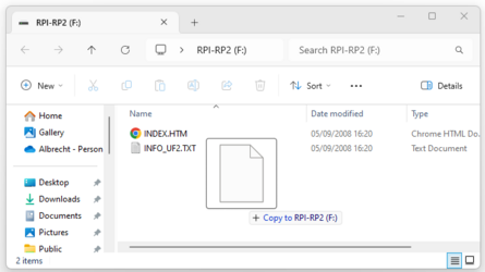
For the Raspberry PI Pico connect the board to the computer and the folder RPI-RP2 shows ups in your file system. For the Arduino Nano Connect RP2040 [https://www.sketching-with-hardware.org/wiki/Arduino_Nano_RP2040_Connect#Install_the_Arduino_Nano_RP2040_Connect_Firmware force the bootloder mode] to upload the .uf2 file. Copy the .uf2 into the folder of the board. | |||
[[File:Cp01.png|x250px]] [[File:Cp02.png|x250px]] | |||
Now you should be able to connect to the board and use the editor. | Now you should be able to connect to the board and use the editor. | ||
If you need more help, here is a [https://learn.adafruit.com/welcome-to-circuitpython/installing-circuitpython more detailed description on the installation process at adafruit.com] | If you need more help, here is a [https://learn.adafruit.com/welcome-to-circuitpython/installing-circuitpython more detailed description on the installation process at adafruit.com] | ||
On the download site there is also a webbased download process - where the browser makes a serial connection to the board. | |||
= CircuitPy Drive = | = CircuitPy Drive = | ||
| Line 19: | Line 21: | ||
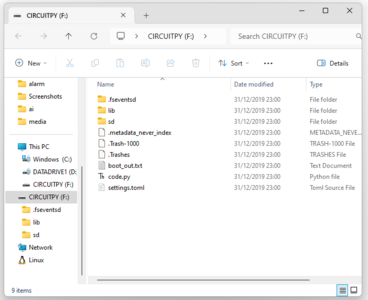
Here you can directly access the code you write and data you safe from your programs. | Here you can directly access the code you write and data you safe from your programs. | ||
[[File:Cp05-usb-drive.png|x300px]] | |||
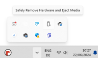
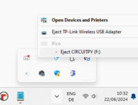
As the board is a USB drive do not just unplug it - use "safe remove" feature of your OS. | |||
[[File:Cp06-safe-remove.png|200px]] | |||
[[File:Cp07-safe-remove.png|200px]] | |||
= Running your first CircuitPython Program = | = Running your first CircuitPython Program = | ||
| Line 38: | Line 34: | ||
To write your program, open code.py and edit it with your code. Once you safe it, it will be automatically excuted. The file name must be code.py or main.py. | To write your program, open code.py and edit it with your code. Once you safe it, it will be automatically excuted. The file name must be code.py or main.py. | ||
Try it out with the following program: | Try it out with the following program. Just use any editor and open code.py. Replace it with the following code and you should see the LED flash. Changes the sleep times. Each time you safe it the new program will be active: | ||
<syntaxhighlight lang="python" line='line'> | <syntaxhighlight lang="python" line='line'> | ||
| Line 48: | Line 44: | ||
led = digitalio.DigitalInOut(board.LED) | led = digitalio.DigitalInOut(board.LED) | ||
led.direction = digitalio.Direction.OUTPUT | led.direction = digitalio.Direction.OUTPUT | ||
while True: | while True: | ||
led.value = False | led.value = False | ||
time.sleep(0.8) | time.sleep(0.8) | ||
| Line 60: | Line 51: | ||
time.sleep(0.2) | time.sleep(0.2) | ||
</syntaxhighlight> | </syntaxhighlight> | ||
<syntaxhighlight lang="python" line='line'> | |||
# check input, switch LED, write on serial line | |||
import board | |||
import digitalio | |||
from digitalio import DigitalInOut, Direction, Pull | |||
import time | |||
led = digitalio.DigitalInOut(board.LED) | |||
led.direction = digitalio.Direction.OUTPUT | |||
switch = DigitalInOut(board.D2) | |||
switch.direction = Direction.INPUT | |||
switch.pull = Pull.UP | |||
while True: | |||
time.sleep(0.2) | |||
if switch.value: | |||
led.value = False | |||
print("Off") | |||
else: | |||
led.value = True | |||
print("On") | |||
</syntaxhighlight> | |||
= Using Libraries = | |||
Here are examples of how to use libraries. | |||
== accelerometer of the Arduino Nano Connect RP2024 == | |||
How to read the accelerometer of the Arduino Nano Connect RP2024. | |||
Download the library (in this case it is in the zip from Adafruit, see [https://learn.adafruit.com/circuitpython-on-the-arduino-nano-rp2040-connect/accelerometer-gyroscope Download Project Bundle]). | |||
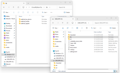
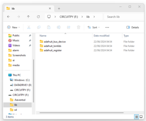
Copy the library folders into the library folder on the USB drive (CIRCUITPY). | |||
[[File:Cp08-lib.png|x250px]] | |||
[[File:Cp09-lib02.png|x250px]] | |||
Now you can use the libraries, e.g. for reading the accelerometer using the adafruit_lsm6ds library. | |||
<syntaxhighlight lang="python" line='line'> | |||
# SPDX-FileCopyrightText: Copyright (c) 2020 Bryan Siepert for Adafruit Industries | |||
# | |||
# SPDX-License-Identifier: MIT | |||
import time | |||
import board | |||
from adafruit_lsm6ds.lsm6dsox import LSM6DSOX | |||
i2c = board.I2C() # uses board.SCL and board.SDA | |||
# i2c = board.STEMMA_I2C() # For using the built-in STEMMA QT connector on a microcontroller | |||
sensor = LSM6DSOX(i2c) | |||
while True: | |||
print("Acceleration: X:%.2f, Y: %.2f, Z: %.2f m/s^2" % (sensor.acceleration)) | |||
print("Gyro X:%.2f, Y: %.2f, Z: %.2f radians/s" % (sensor.gyro)) | |||
print("") | |||
time.sleep(0.5) | |||
</syntaxhighlight> | |||
for more details see: [https://learn.adafruit.com/circuitpython-on-the-arduino-nano-rp2040-connect/accelerometer-gyroscope on how to use the onboard IMU of the Arduino Nano RP2040 Connect (LSM6DSOXTR)] | |||
== Keyboard emulator == | |||
[https://learn.adafruit.com/circuitpython-essentials/circuitpython-hid-keyboard-and-mouse for more details on the mouse and keyboard emulator see the Adafruit page] | |||
We have also an [[KeyboardEmulator | example, where the IMU of the Arduino Nano Connect RP2040 is read and strings are send to the computer]]. | |||
<syntaxhighlight lang="python" line='line'> | |||
# SPDX-FileCopyrightText: 2018 Kattni Rembor for Adafruit Industries | |||
# | |||
# SPDX-License-Identifier: MIT | |||
"""CircuitPython Essentials HID Keyboard example""" | |||
import time | |||
import board | |||
import digitalio | |||
from digitalio import DigitalInOut, Direction, Pull | |||
import usb_hid | |||
from adafruit_hid.keyboard import Keyboard | |||
from adafruit_hid.keyboard_layout_us import KeyboardLayoutUS | |||
from adafruit_hid.keycode import Keycode | |||
led = digitalio.DigitalInOut(board.LED) | |||
led.direction = digitalio.Direction.OUTPUT | |||
switch = DigitalInOut(board.D2) | |||
switch.direction = Direction.INPUT | |||
switch.pull = Pull.UP | |||
# The keyboard object! | |||
time.sleep(1) # Sleep for a bit to avoid a race condition on some systems | |||
keyboard = Keyboard(usb_hid.devices) | |||
keyboard_layout = KeyboardLayoutUS(keyboard) # We're in the US :) | |||
while True: | |||
time.sleep(2) | |||
if switch.value: | |||
led.value = False | |||
print("Off") | |||
else: | |||
led.value = True | |||
print("On") | |||
keyboard_layout.write("Hi There") # ...Print the string | |||
</syntaxhighlight> | |||
= Finding your PIN names - Pin mapping script = | |||
CircuitPython uses it own names which makes it easier to use the same code on different boards. But this requires you to first find out which PINs on your physical board map to the logical pins in the program code. | |||
There is a [https://learn.adafruit.com/circuitpython-essentials/circuitpython-pins-and-modules pin mapping scriptt avaiable for this at Adafruit]. You can download the [https://learn.adafruit.com/circuitpython-essentials/circuitpython-pins-and-modules project bundel there]. Here is the script, too. And below are the mappings for the Arduino Nano Connect RP2024 and the Raspberry Pi Pico | |||
<syntaxhighlight lang="python" line='line'> | |||
# SPDX-FileCopyrightText: 2020 anecdata for Adafruit Industries | |||
# SPDX-FileCopyrightText: 2021 Neradoc for Adafruit Industries | |||
# SPDX-FileCopyrightText: 2021-2023 Kattni Rembor for Adafruit Industries | |||
# SPDX-FileCopyrightText: 2023 Dan Halbert for Adafruit Industries | |||
# | |||
# SPDX-License-Identifier: MIT | |||
"""CircuitPython Essentials Pin Map Script""" | |||
import microcontroller | |||
import board | |||
try: | |||
import cyw43 # raspberrypi | |||
except ImportError: | |||
cyw43 = None | |||
board_pins = [] | |||
for pin in dir(microcontroller.pin): | |||
if (isinstance(getattr(microcontroller.pin, pin), microcontroller.Pin) or | |||
(cyw43 and isinstance(getattr(microcontroller.pin, pin), cyw43.CywPin))): | |||
pins = [] | |||
for alias in dir(board): | |||
if getattr(board, alias) is getattr(microcontroller.pin, pin): | |||
pins.append(f"board.{alias}") | |||
# Add the original GPIO name, in parentheses. | |||
if pins: | |||
# Only include pins that are in board. | |||
pins.append(f"({str(pin)})") | |||
board_pins.append(" ".join(pins)) | |||
for pins in sorted(board_pins): | |||
print(pins) | |||
</syntaxhighlight> | |||
When you run the script on a specific controller you get a text ouput that is the mapping. | |||
== CircuitPython Pin Mapping for Arduino Nano Connect RP2024 == | |||
<syntaxhighlight lang="python" line='line'> | |||
board.A0 (GPIO26) | |||
board.A1 (GPIO27) | |||
board.A2 (GPIO28) | |||
board.A3 (GPIO29) | |||
board.A4 board.SDA (GPIO12) | |||
board.A5 board.SCL (GPIO13) | |||
board.CS1 board.ESP_CS (GPIO9) | |||
board.D0 board.TX (GPIO0) | |||
board.D1 board.RX (GPIO1) | |||
board.D10 (GPIO5) | |||
board.D11 board.MOSI (GPIO7) | |||
board.D12 board.MISO (GPIO4) | |||
board.D13 board.LED board.SCK (GPIO6) | |||
board.D2 (GPIO25) | |||
board.D3 (GPIO15) | |||
board.D4 (GPIO16) | |||
board.D5 (GPIO17) | |||
board.D6 (GPIO18) | |||
board.D7 (GPIO19) | |||
board.D8 (GPIO20) | |||
board.D9 (GPIO21) | |||
board.ESP_BUSY (GPIO10) | |||
board.ESP_GPIO0 (GPIO2) | |||
board.ESP_RESET (GPIO3) | |||
board.INT1 (GPIO24) | |||
board.MICROPHONE_CLOCK (GPIO23) | |||
board.MICROPHONE_DATA (GPIO22) | |||
board.MISO1 (GPIO8) | |||
board.MOSI1 (GPIO11) | |||
board.SCK1 (GPIO14) | |||
</syntaxhighlight> | |||
== CircuitPython Pin Mapping for Raspberry PI Pico == | |||
<syntaxhighlight lang="python" line='line'> | |||
board.A0 board.GP26 board.GP26_A0 (GPIO26) | |||
board.A1 board.GP27 board.GP27_A1 (GPIO27) | |||
board.A2 board.GP28 board.GP28_A2 (GPIO28) | |||
board.A3 board.VOLTAGE_MONITOR (GPIO29) | |||
board.GP0 (GPIO0) | |||
board.GP1 (GPIO1) | |||
board.GP10 (GPIO10) | |||
board.GP11 (GPIO11) | |||
board.GP12 (GPIO12) | |||
board.GP13 (GPIO13) | |||
board.GP14 (GPIO14) | |||
board.GP15 (GPIO15) | |||
board.GP16 (GPIO16) | |||
board.GP17 (GPIO17) | |||
board.GP18 (GPIO18) | |||
board.GP19 (GPIO19) | |||
board.GP2 (GPIO2) | |||
board.GP20 (GPIO20) | |||
board.GP21 (GPIO21) | |||
board.GP22 (GPIO22) | |||
board.GP23 board.SMPS_MODE (GPIO23) | |||
board.GP24 board.VBUS_SENSE (GPIO24) | |||
board.GP25 board.LED (GPIO25) | |||
board.GP3 (GPIO3) | |||
board.GP4 (GPIO4) | |||
board.GP5 (GPIO5) | |||
board.GP6 (GPIO6) | |||
board.GP7 (GPIO7) | |||
board.GP8 (GPIO8) | |||
board.GP9 (GPIO9) | |||
</syntaxhighlight> | |||
= Install the Mu Editor = | |||
Follow the instructions for [https://learn.adafruit.com/welcome-to-circuitpython/installing-mu-editor installting the Mu Editor]. | |||
* download software from [https://codewith.mu/en/download codewith.mu] | |||
* Install it on your system | |||
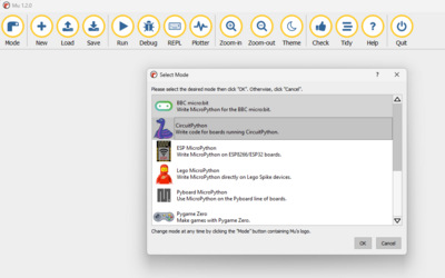
* On first start up select CircuitPython as Mode | |||
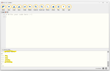
[[File:Cp3-mu.png|x250px]] | |||
* Test if it works in the CircuitPython REPL console | |||
[[File:Cp4-mu.png|x250px]] | |||
Latest revision as of 02:59, 18 July 2025
Introduction and step by step tutorial from Adafruit
Installing CircuitPython
Go to circuitpython.org/downloads and download the version for your board.
For the Raspberry PI Pico connect the board to the computer and the folder RPI-RP2 shows ups in your file system. For the Arduino Nano Connect RP2040 force the bootloder mode to upload the .uf2 file. Copy the .uf2 into the folder of the board.
Now you should be able to connect to the board and use the editor.
If you need more help, here is a more detailed description on the installation process at adafruit.com
On the download site there is also a webbased download process - where the browser makes a serial connection to the board.
CircuitPy Drive
After installing CircuitPython on the board and reconnecting the board, it should show up as a USB drive on your computer with the name CircuitPy.
Here you can directly access the code you write and data you safe from your programs.
As the board is a USB drive do not just unplug it - use "safe remove" feature of your OS.
Running your first CircuitPython Program
In the file system of the board (that shows up as USB Drive CIRCUITPY) there is a file code.py.
To write your program, open code.py and edit it with your code. Once you safe it, it will be automatically excuted. The file name must be code.py or main.py.
Try it out with the following program. Just use any editor and open code.py. Replace it with the following code and you should see the LED flash. Changes the sleep times. Each time you safe it the new program will be active:
# write on serial line and blink onbaord LED
import board
import digitalio
import time

led = digitalio.DigitalInOut(board.LED)
led.direction = digitalio.Direction.OUTPUT

while True:
    led.value = False
    time.sleep(0.8)
    led.value = True
    time.sleep(0.2)
# check input, switch LED, write on serial line
import board
import digitalio
from digitalio import DigitalInOut, Direction, Pull
import time

led = digitalio.DigitalInOut(board.LED)
led.direction = digitalio.Direction.OUTPUT

switch = DigitalInOut(board.D2)
switch.direction = Direction.INPUT
switch.pull = Pull.UP

while True:
    time.sleep(0.2)
    if switch.value:
        led.value = False
        print("Off")
    else:
        led.value = True
        print("On")
Using Libraries
Here are examples of how to use libraries.
accelerometer of the Arduino Nano Connect RP2024
How to read the accelerometer of the Arduino Nano Connect RP2024.
Download the library (in this case it is in the zip from Adafruit, see Download Project Bundle).
Copy the library folders into the library folder on the USB drive (CIRCUITPY).
Now you can use the libraries, e.g. for reading the accelerometer using the adafruit_lsm6ds library.
# SPDX-FileCopyrightText: Copyright (c) 2020 Bryan Siepert for Adafruit Industries
#
# SPDX-License-Identifier: MIT
import time
import board
from adafruit_lsm6ds.lsm6dsox import LSM6DSOX

i2c = board.I2C()  # uses board.SCL and board.SDA
# i2c = board.STEMMA_I2C()  # For using the built-in STEMMA QT connector on a microcontroller
sensor = LSM6DSOX(i2c)

while True:
    print("Acceleration: X:%.2f, Y: %.2f, Z: %.2f m/s^2" % (sensor.acceleration))
    print("Gyro X:%.2f, Y: %.2f, Z: %.2f radians/s" % (sensor.gyro))
    print("")
    time.sleep(0.5)
for more details see: on how to use the onboard IMU of the Arduino Nano RP2040 Connect (LSM6DSOXTR)
Keyboard emulator
for more details on the mouse and keyboard emulator see the Adafruit page
We have also an example, where the IMU of the Arduino Nano Connect RP2040 is read and strings are send to the computer.
# SPDX-FileCopyrightText: 2018 Kattni Rembor for Adafruit Industries
#
# SPDX-License-Identifier: MIT

"""CircuitPython Essentials HID Keyboard example"""
import time
import board
import digitalio
from digitalio import DigitalInOut, Direction, Pull
import usb_hid
from adafruit_hid.keyboard import Keyboard
from adafruit_hid.keyboard_layout_us import KeyboardLayoutUS
from adafruit_hid.keycode import Keycode

led = digitalio.DigitalInOut(board.LED)
led.direction = digitalio.Direction.OUTPUT

switch = DigitalInOut(board.D2)
switch.direction = Direction.INPUT
switch.pull = Pull.UP

# The keyboard object!
time.sleep(1)  # Sleep for a bit to avoid a race condition on some systems
keyboard = Keyboard(usb_hid.devices)
keyboard_layout = KeyboardLayoutUS(keyboard)  # We're in the US :)


while True:
    time.sleep(2)
    if switch.value:
        led.value = False
        print("Off")
    else:
        led.value = True
        print("On")
        keyboard_layout.write("Hi There")  # ...Print the string
Finding your PIN names - Pin mapping script
CircuitPython uses it own names which makes it easier to use the same code on different boards. But this requires you to first find out which PINs on your physical board map to the logical pins in the program code.
There is a pin mapping scriptt avaiable for this at Adafruit. You can download the project bundel there. Here is the script, too. And below are the mappings for the Arduino Nano Connect RP2024 and the Raspberry Pi Pico
# SPDX-FileCopyrightText: 2020 anecdata for Adafruit Industries
# SPDX-FileCopyrightText: 2021 Neradoc for Adafruit Industries
# SPDX-FileCopyrightText: 2021-2023 Kattni Rembor for Adafruit Industries
# SPDX-FileCopyrightText: 2023 Dan Halbert for Adafruit Industries
#
# SPDX-License-Identifier: MIT

"""CircuitPython Essentials Pin Map Script"""
import microcontroller
import board
try:
    import cyw43  # raspberrypi
except ImportError:
    cyw43 = None

board_pins = []
for pin in dir(microcontroller.pin):
    if (isinstance(getattr(microcontroller.pin, pin), microcontroller.Pin) or
        (cyw43 and isinstance(getattr(microcontroller.pin, pin), cyw43.CywPin))):
        pins = []
        for alias in dir(board):
            if getattr(board, alias) is getattr(microcontroller.pin, pin):
                pins.append(f"board.{alias}")
        # Add the original GPIO name, in parentheses.
        if pins:
            # Only include pins that are in board.
            pins.append(f"({str(pin)})")
            board_pins.append(" ".join(pins))

for pins in sorted(board_pins):
    print(pins)
When you run the script on a specific controller you get a text ouput that is the mapping.
CircuitPython Pin Mapping for Arduino Nano Connect RP2024
board.A0 (GPIO26)
board.A1 (GPIO27)
board.A2 (GPIO28)
board.A3 (GPIO29)
board.A4 board.SDA (GPIO12)
board.A5 board.SCL (GPIO13)
board.CS1 board.ESP_CS (GPIO9)
board.D0 board.TX (GPIO0)
board.D1 board.RX (GPIO1)
board.D10 (GPIO5)
board.D11 board.MOSI (GPIO7)
board.D12 board.MISO (GPIO4)
board.D13 board.LED board.SCK (GPIO6)
board.D2 (GPIO25)
board.D3 (GPIO15)
board.D4 (GPIO16)
board.D5 (GPIO17)
board.D6 (GPIO18)
board.D7 (GPIO19)
board.D8 (GPIO20)
board.D9 (GPIO21)
board.ESP_BUSY (GPIO10)
board.ESP_GPIO0 (GPIO2)
board.ESP_RESET (GPIO3)
board.INT1 (GPIO24)
board.MICROPHONE_CLOCK (GPIO23)
board.MICROPHONE_DATA (GPIO22)
board.MISO1 (GPIO8)
board.MOSI1 (GPIO11)
board.SCK1 (GPIO14)
CircuitPython Pin Mapping for Raspberry PI Pico
board.A0 board.GP26 board.GP26_A0 (GPIO26)
board.A1 board.GP27 board.GP27_A1 (GPIO27)
board.A2 board.GP28 board.GP28_A2 (GPIO28)
board.A3 board.VOLTAGE_MONITOR (GPIO29)
board.GP0 (GPIO0)
board.GP1 (GPIO1)
board.GP10 (GPIO10)
board.GP11 (GPIO11)
board.GP12 (GPIO12)
board.GP13 (GPIO13)
board.GP14 (GPIO14)
board.GP15 (GPIO15)
board.GP16 (GPIO16)
board.GP17 (GPIO17)
board.GP18 (GPIO18)
board.GP19 (GPIO19)
board.GP2 (GPIO2)
board.GP20 (GPIO20)
board.GP21 (GPIO21)
board.GP22 (GPIO22)
board.GP23 board.SMPS_MODE (GPIO23)
board.GP24 board.VBUS_SENSE (GPIO24)
board.GP25 board.LED (GPIO25)
board.GP3 (GPIO3)
board.GP4 (GPIO4)
board.GP5 (GPIO5)
board.GP6 (GPIO6)
board.GP7 (GPIO7)
board.GP8 (GPIO8)
board.GP9 (GPIO9)
Install the Mu Editor
Follow the instructions for installting the Mu Editor.
- download software from codewith.mu
- Install it on your system
- On first start up select CircuitPython as Mode
- Test if it works in the CircuitPython REPL console
